What is an Airend (Screw Element)?
In rotary screw compressors, the airend (screw element) is the core component where the actual compression process occurs. The operational efficiency of this unit, the precision of the materials used, and the rigor of maintenance protocols directly dictate the overall performance of the compressor. Understanding the internal structure of the airend and its potential failure mechanisms is critical for maintaining both operational efficiency and long-term operating costs.
11/27/20252 min read
1. Airend Structure and Operating Principle
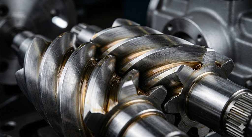
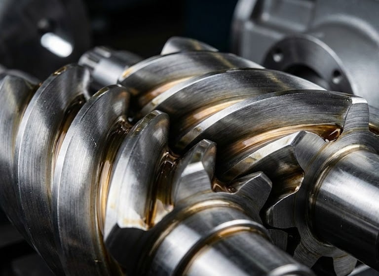
The airend consists of two intermeshing helical rotors. Utilizing the positive displacement principle, the rotors draw in, transport, and compress air. The compression process occurs in four fundamental stages:
Intake: The vacuum created by the rotor movement draws atmospheric air into the rotor flutes.
Transfer: The air moves toward the discharge end within the sealed volume between the rotors.
Compression and Oil Injection: As the volume decreases, the pressure rises. At this stage, injected oil:
Controls the heat of compression,
Creates a seal between the rotors and the casing,
Lubricates the bearings and rotor surfaces.
Discharge: The pressurized air-oil mixture is directed to the discharge line and transferred to the rest of the system. This design allows rotary screw compressors to provide a stable, low-vibration airflow.
2. Critical Components in Airend Design
Airend components are manufactured with micron-level tolerances; therefore, material selection and machining precision directly impact performance.
Rotor Pair: The Male Rotor receives the drive directly, while the Female Rotor operates in synchronization. The rotor profile is the primary factor determining air volume and internal leakage.
Bearings: * Radial bearings protect rotors from horizontal loads.
Axial (thrust) bearings handle the axial forces generated by the helical design. If bearings exceed their tolerances, it leads to rotor-to-casing contact and catastrophic damage.
Housing (Casing): The clearance between the rotor and the housing is a critical parameter for efficiency. An increase in this gap over time leads to a drop in compression efficiency.
3. Common Airend Failure Mechanisms
Most failures depend on operating conditions, oil quality, and maintenance discipline.
Lubrication Issues: Low oil levels, incorrect viscosity, or contaminated oil cause metal surface wear, temperature spikes, and rotor seizure.
Bearing Failure: Reaching the end of bearing service life or inadequate lubrication results in rotors rubbing against the housing, causing severe geometric deformation.
Overheating: Continuous operation above 90°C leads to thermal expansion, closing the tolerances and increasing friction.
Contamination: If the air filter fails to perform, dust and particles act as abrasives on rotor surfaces, causing loss of efficiency and long-term damage.
4. Symptoms of Failure
The following signs may indicate an emerging airend problem:
Abnormal metallic noises or unusual humming.
Higher than normal discharge temperatures.
Increased time to reach pressure or loss of FAD (Free Air Delivery).
Increased vibration levels. Early intervention when these symptoms appear prevents major damage and high repair costs.
5. Airend Overhaul Process
An overhaul is a technical procedure aimed at restoring the airend to its original factory tolerances. It is not a simple repair.
Disassembly and Inspection: Rotor surfaces, bearing seats, and internal housing surfaces are inspected using micron-level measuring equipment.
Repair and Resurfacing: Surfaces with scratches or wear are brought back to original tolerances through grinding or coating methods.
Assembly and Setting: New bearings and shaft seals are installed. Axial clearances are precisely adjusted using shimming methods.
Testing: The reassembled unit is tested for torque, temperature, noise, and vibration to verify stable operation.